Improving Vehicular Networking Reliability and Efficiency in the Context of Platooning Applications
Song Gao
Committee:
Alvin Lim (Chair), Saad Biaz, Hari Narayanan, Xiao Qin
Final Oral Exam
University Reader:
Shiwen Mao
Overview
Background
Squirrel: A Wireless Emulator
Interframe Compression Transmission Layer
Future Work
Conclusions
Contributions
- A wireless emulation infrastructure for testing real-world networking applications and protocols
- An inter-frame compression method for reducing bandwidth consumption in vehicular networks
- An adaptive ICTL that achieves 50% bandwidth reduction
- Reduced bandwidth consumption helps increase delivery ratio
Overview
Background
Squirrel: A Wireless Emulator
Interframe Compression Transmission Layer
Future Work
Conclusions
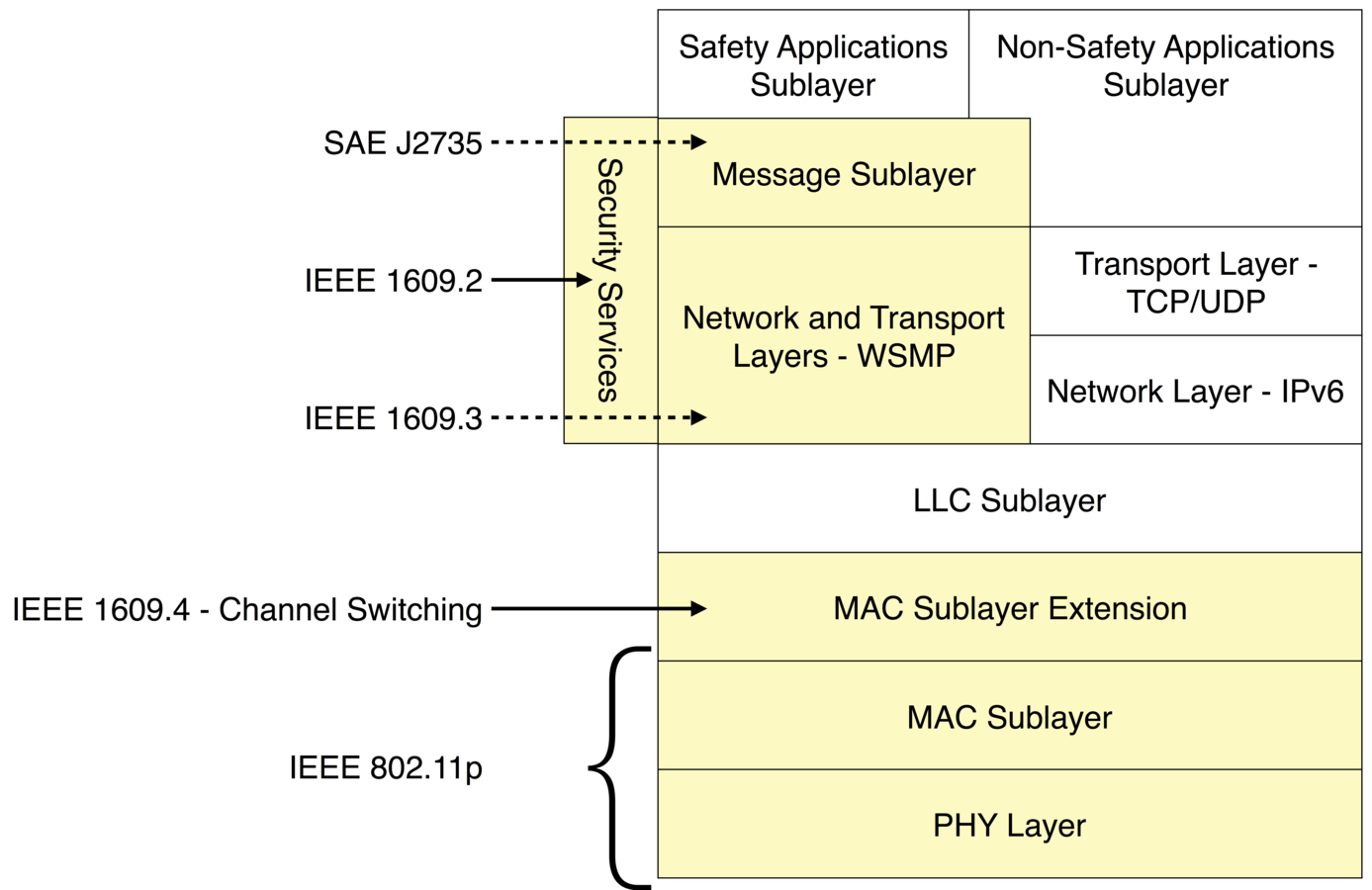
DSRC Protocol Suite
5.9 GHz / 10 MHz
OCB
1 CCH + 6 SCH
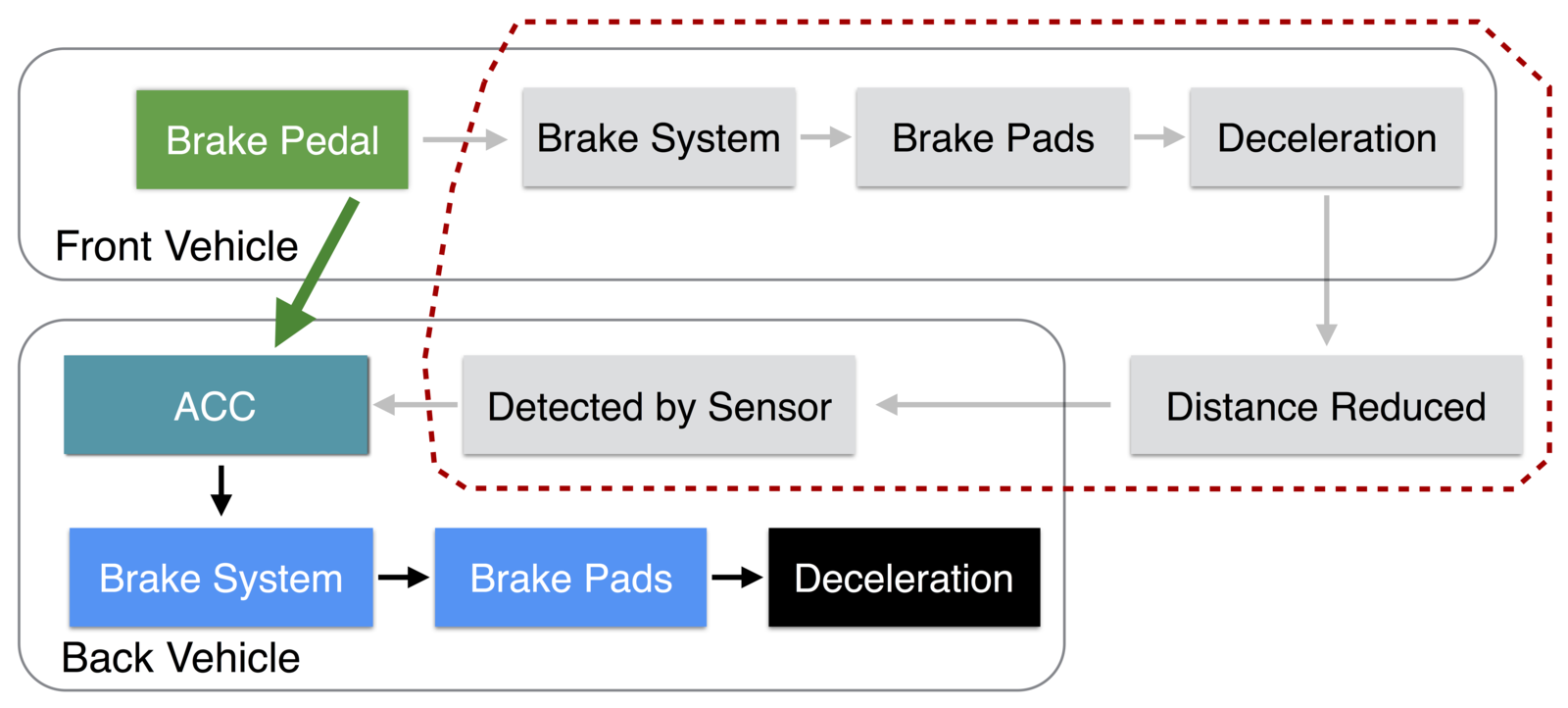
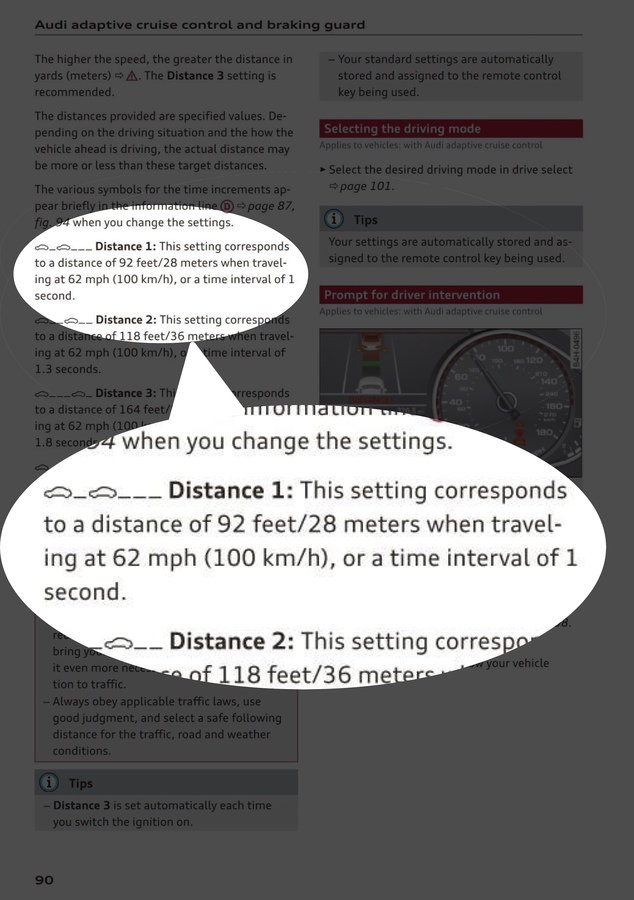
Vehicle Platooning
(Cooperative Adaptive Cruise Control)


CC
ACC
CACC
Vehicular Platooning
(Cooperative Adaptive Cruise Control)
Vehicular Platooning
ACC
CACC
| Following Distance | 6 feet |
| Speed | 45 mph |
| Time Interval | 0.1 second |
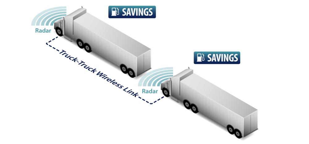
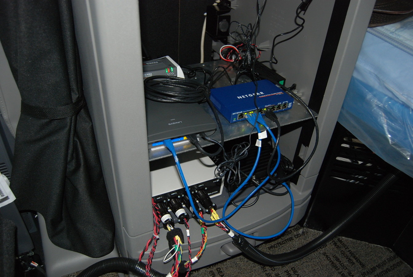
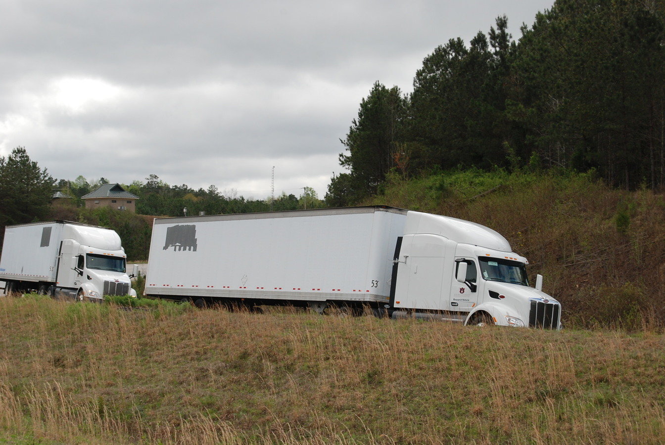
Real-World DSRC in Platooning Scenarios
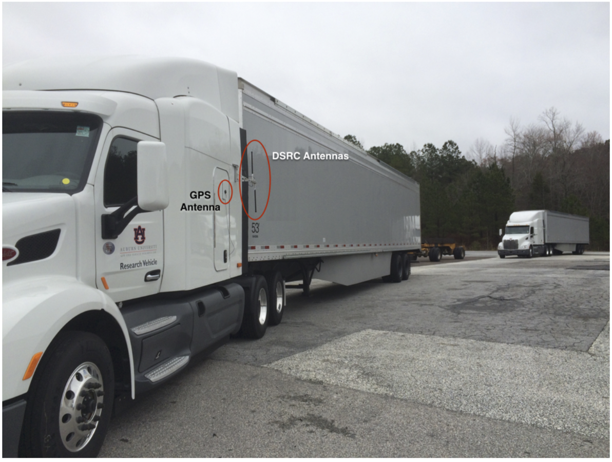
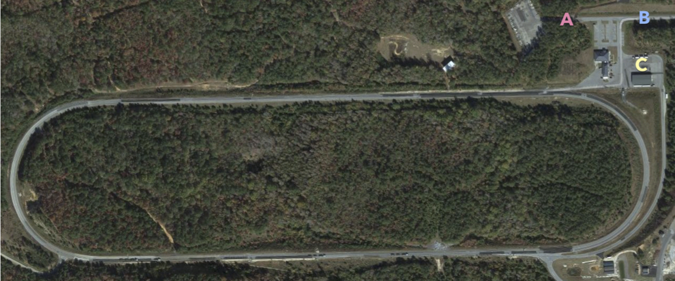
- Two trucks with trailers installed
- Dual antenna: one on each side of tractor
- Front -> Back (broadcast), delivery ratio measured
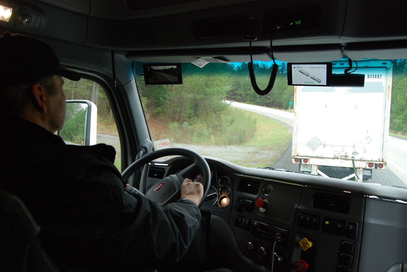
Real-World DSRC in Platooning Scenarios
Delivery ratio can be easily affected:
- Front vehicle turning: outside antenna is blocked by the vehicle body and results in poor delivery ratio
- On straight road: some terrain can affect delivery ratio significantly
- On hilly road: vehicle needs to rely on terrain’s reflection because antennas are not parallel
Using both antennas alternately significantly increase (pairwise) delivery ratio in all scenarios
- >= 90% for up to 6 Mbps
Overview
Background
Squirrel: A Wireless Emulator
Interframe Compression Transmission Layer
Future Work
Conclusions
Algorithm and Protocol Validation
Formal Analysis
Experimental Study
Real-world Experiments
Simulation
Emulation
Real-world Experiments
Advantages:
- Authentic Results
- Closest to Production Environment
Disadvantages:
- High cost (hardware, human hours)
- Not scalable
- Solution needs to be sufficiently mature


slow vehicle
Simulation
Advantages:
- Low cost
- Extremely scalable
- Support arbitrary maturity level
Disadvantages:
- Accuracy is determined by model quality
- Not deployable to real-world
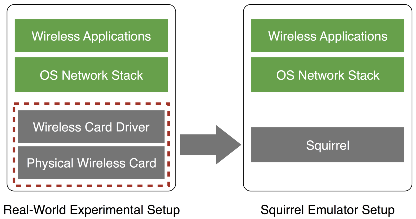
Emulation
Real-world Components
- Good balance between real-world experiments and simulations
- Hard-to-scale part is emulated (models)
- Non-emlulated part is deployable to real-world
Emulated Models
Challenges:
- Good system design
- Proper channel interference modeling
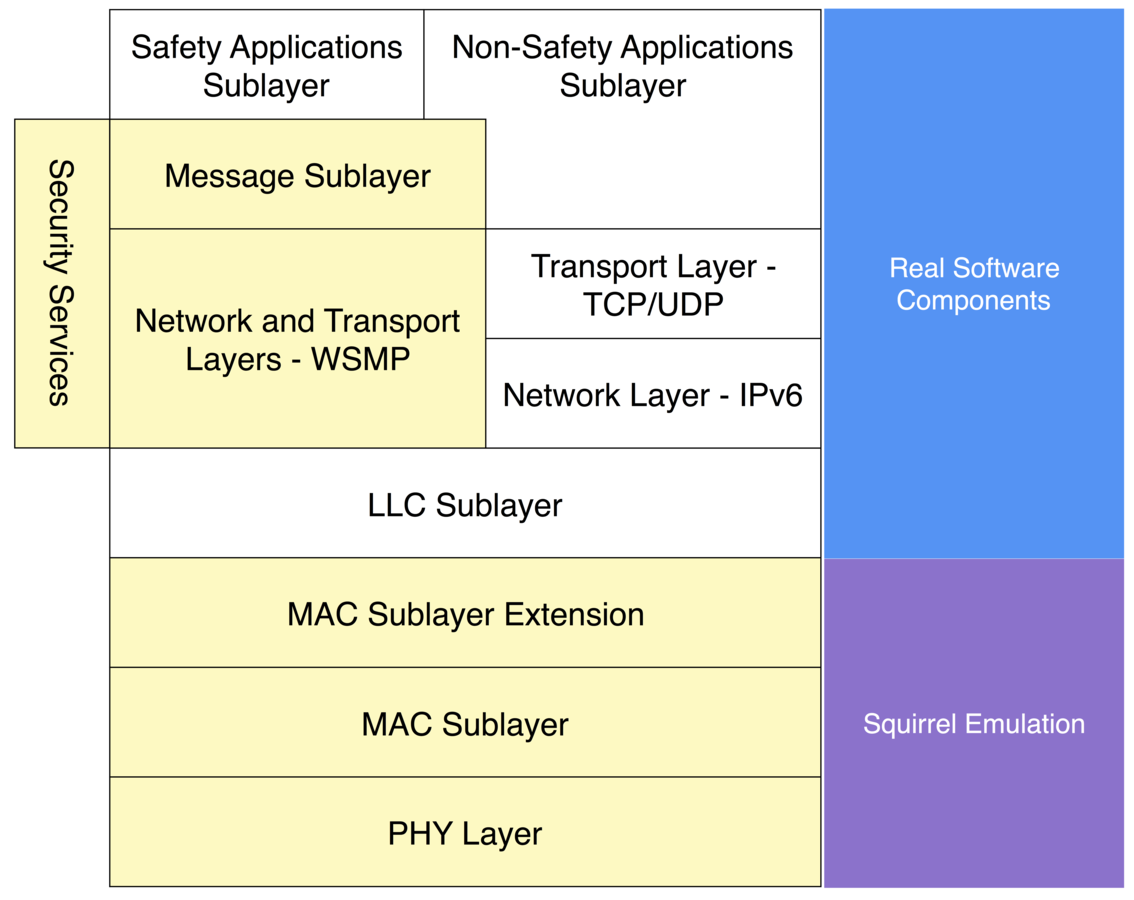
Squirrel Concept
Squirrel and DSRC
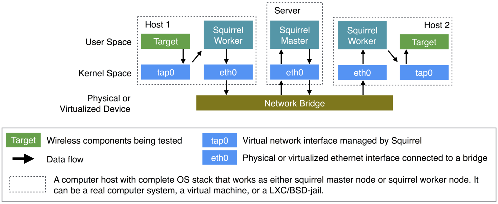
Squirrel Architecture
CSMA/CA Model
Challenge:
- Modeling channel occupation and interference properly
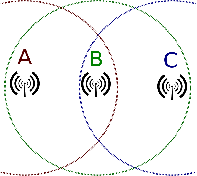
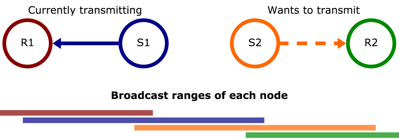
Example: 1. Hidden node problem; 2. Exposed node problem
CSMA/CA Model
CSMA/CA Model
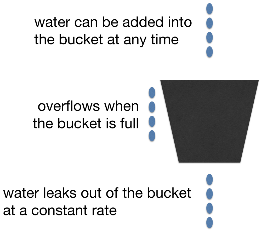
Solution:
- One leaky bucket per node
- Water -> time durations
- "Water" is added whenever channel used around the node
- Drop frames when bucket is full
RPC Updated Mobility Manager
- Position Manager exposed as RPC Service
- Position Updating delegated to a different process
Effectiveness Test
Same test on Android tablets and squirrel emulated nodes:
Android:
- 4 Nexus 7 tablets with modified Android kernel
- placed next to each other
-
iperf UDP throughput test:
- node 1 to node 2 from 0th sec until 30th sec
- node 3 to node 4 from 10th sec until 20th sec
Squirrel:
- 4 emulated nodes running Linux networking stack
- emulated distance set to 150, with interference range set to 300k
- iperf UDP throughput test:
- same test design
Effectiveness Test
Throughput Test
- Deployed on a single workstation
- 6-cores
- no hyper threading
- 12 (6 pair) of emulated nodes
- iperf UDP traffic
- 500 Mbps demanded
Throughput Test
Related Work
- Dynamic Switch [20]: impossible to support interference modeling;
- EMANE [21]: very similar; complex and no vehicular networking support.
[20] T. Lin, “Mobile ad-hoc network routing protocols: methodologies and applications,” Ph.D. dissertation, Virginia Polytechnic Institute and State University, 2004.
[21] U.S. Naval Research Lab. Extendable mobile ad-hoc network emulator (emane). [Online]. Available: http://www.nrl.navy.mil/itd/ncs/products/emane
Overview
Background
Squirrel: A Wireless Emulator
Interframe Compression Transmission Layer
Future Work
Conclusions
DSRC Congestion
- Uses 10 MHz channels
- Needs 2 antennas
- Longer distance -> bigger interference range
- Safety applications require continuous real-time data
DSRC will have congestion problem once fully deployed
Case Study: Busy Interstate Segment
| Average Following Distance | 20 meters |
| Platooning Message | 150 bytes |
| Number of Lanes | 5 per direction |
| Interference Range | 400 meters |
| MAC Layer Data Rate | 6 Mbps |
| Platooning Message Rate | 20 Hz |
(I-285)
Assumptions:
Case Study: Busy Interstate Segment
Interference distance: 400 * 2 = 800m
# of cars generating interference per lane: 800m / 20m = 40
# of cars generating interference: 40/lane * 10lanes = 400
Demanded message rate: 20 Hz * 400 = 8,000 Hz
Demanded chan. bandwidth: 8KHz * 150B = 1.2MB/s (9.6 Mbps)
9.6 Mbps >> MAC data rate (6 Mbps)
plus channel switching, CSMA overhead, etc.
Interframe Compression in Video Codec
Introduced in video compression algorithms
Assumptions:
- Consecutive frames are similar
- Minor image degradation doesn't affect video quality
Core Ideas:
- I-Frame: complete frame
- P-Frame: forward prediction (much smaller)
- B-Frame: bi-directional prediction (much smaller)
- Encoding: IBBPBBP...PBBI
Interframe and Platooning
Assumption:
- Consecutive messages are similar
- Minor error is not acceptable
- Transport is usually unreliable
Video interframe compression cannot be applied directly.
Solution:
- Replace lossy prediction frames with lossless differential frames
- Less differential frames between complete frames
Interframe Compression Transmission Layer
- Between applications and WSMP layer
- Automatically handles encoding and decoding
- Two frame types: Key Frame & Differential Frame
| Reserved | Frame Type | Compression Options | Frame ID | Payload |
|---|---|---|---|---|
| 4 bits | 4 bits | 8 bits | 16 bits | variable |
Frame Layout:
ICTL Differential Frame
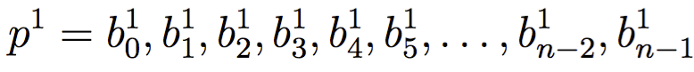
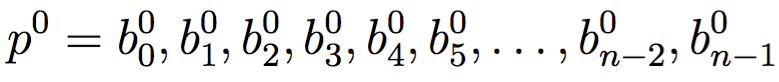

Previous:
Current:
Differential:
Lower entropy, more compressible
XOR
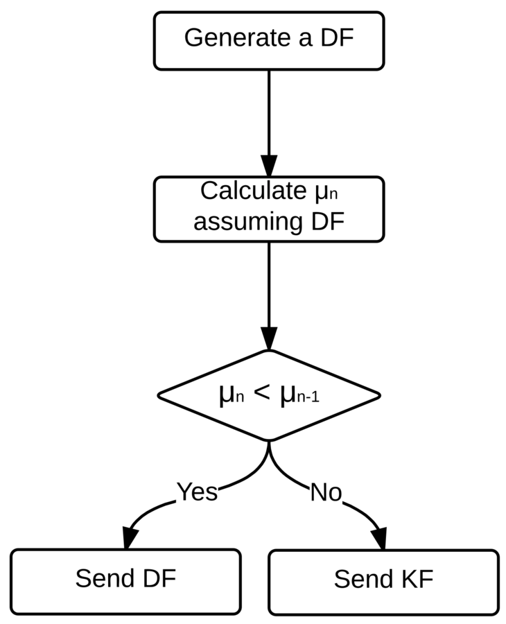
ICTL Encoding & Decoding
Prerequisite: Every node needs to keep a list of recently received Key Frames
Encoding (Transmitter):
- Key Frames:
- Add frame to recent KFs list
- Prepend ICTL header
- Differential Frames:
- Construct the DF (XOR) from one of recently sent KFs
- Compress DF
- Prepend ICTL header
Decoding (Receiver):
- Key Frames:
- Parse ICTL header
- Add the KF to recent KFs list
- Differential Frames:
- Parse ICTL header
- Decompress DF
- Construct original message using the DF and referenced KF
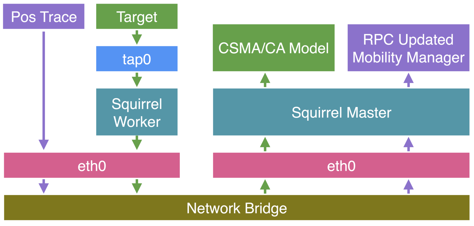
ICTL Implementation and Experimental Setup
- Platooning Trace File Playback
- GPS locations -> RPC updated with squirrel
- DSRC transmission -> goes through squirrel
- Deployed on a single workstation
- CoreOS / Rkt
- Trigering Congestion
- Replicated messages
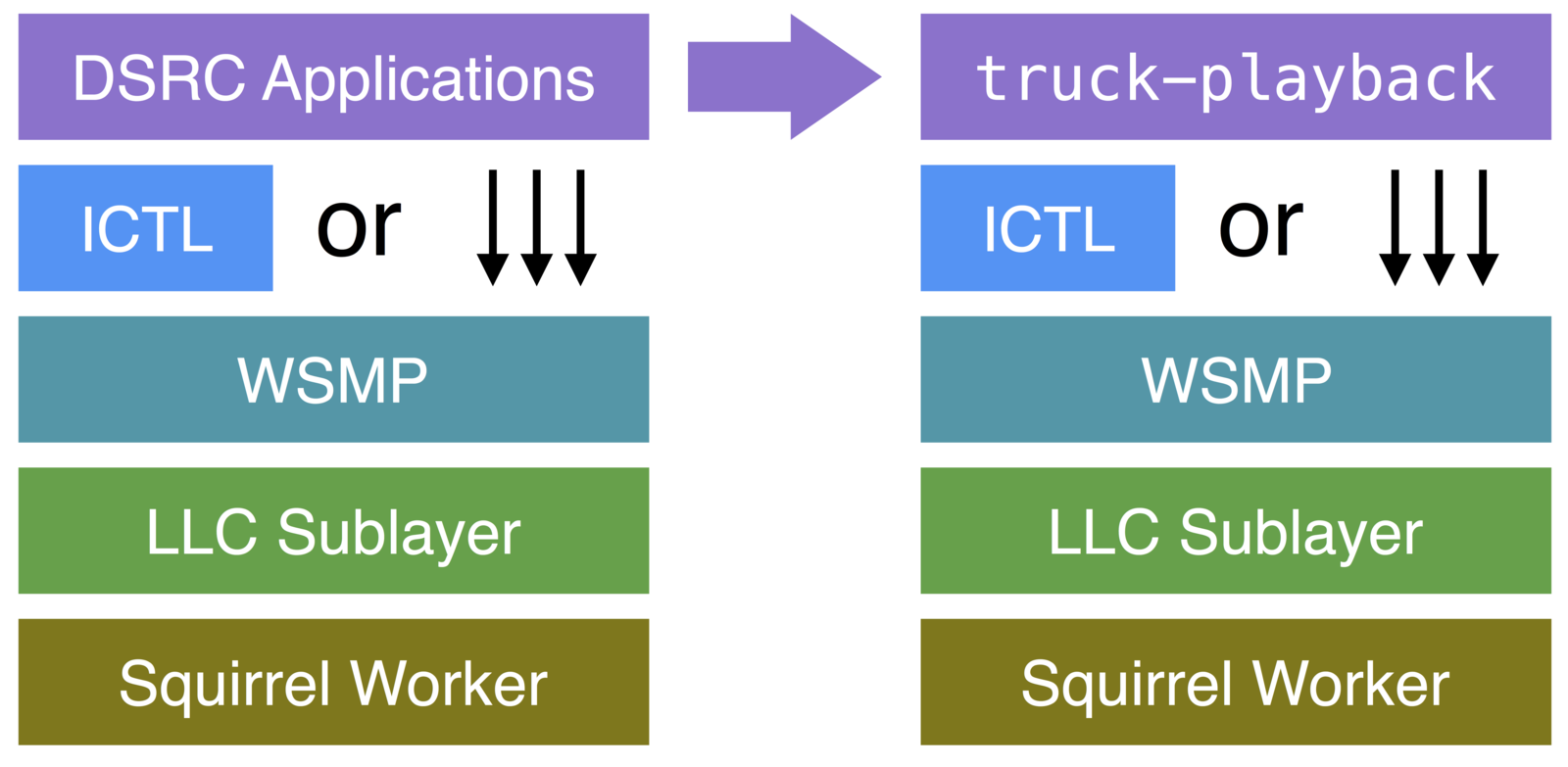
- Implemented as a simple interface ictl.Endpoint
- Encode() / Decode()
ICTL First Glance
ICTL Performance Studies
- Cycle Length and Application Delivery Ratio
- Location and Bandwidth
- curved roads vs straight roads
- Payload Compression
- Cycle Length and Bandwidth
Cycle Length and Application Delivery Ratio
- ICTL Cycle:
- [KF-DF-DF]-[KF-DF-DF]
- Cycle Length (CL)
- # of frames in a cycle. e.g. CL([KF-DF-DF])=3
- Application Delivery Ratio (ADR)
- delivery ratio at application layer (above ICTL)
- Network Delivery Ratio (NDR)
- delivery ratio below ICTL
Definitions:
Cycle Length and Application Delivery Ratio
With in an ICTL Cycle, [KF-DF-DF-...-DF]:
- At probability of 1-NDR, the KF is lost:
- expected # of deliveries in ICTL Cycle: 0
- At probability of NDR, the KF is delivered:
- expected # of deliveries in ICTL Cycle: 1+(m-1)*NDR
Cycle Length and Application Delivery Ratio
Location and Bandwidth
Does ICTL use more bandwidth at curved roads?
Payload Compression
Does it make sense to try each compression algorithm for each individual frame?
Cycle Length and Bandwidth
Longer CL != Less Bandwidth

Adaptive ICTL
- Global Optimal: infeasible
- Based on local metric: average frame size
Adaptive ICTL
Adaptive ICTL Bandwidth Consumption
Adaptive ICTL ADR: 4 nodes
Adaptive ICTL ADR: 6 nodes
Adaptive ICTL ADR: 10 nodes
Adaptive ICTL ADR: 12 nodes
Adaptive ICTL ADR: aggregated

ICTL Latency
| Read 1MB sequentially from memory | 0.25 ms |
| Round trip within same data center | 0.5 ms |
| ICTL | < 1 ms |
| DSRC On-board WSM | normally 1ms ~ 5ms |
| Round trip ICMP ping to AU_WiFi AP | ~ 2.5 ms |
Related Work
[34] Z. Wang and M. Hassan: “How much of dsrc is available for non-safety use?” VANET ’08
[35] C.-L. Huang, Y. Fallah, et. al.: “Adaptive intervehicle communication control for cooperative safety systems,” Network, IEEE, 2010.
[36] Y. Fallah, C. Huang, et. al.: “Congestion control based on channel occupancy in vehicular broadcast networks,” VTC '10
non-safety use of DSRC may have to be severely restricted during peak hours of traffic.
adapts communication rate and power based on the dynamics of a vehicular network and safety-driven tracking process.
a closed loop congestion monitoring and control based on limited feedback from the network.
[38] S. International, “SAE J2945.1 On-Board System Requirements for V2V Safety Com- munications,”
inspects channel busy percentage and packet error rate, to make transmission decisions, including transmission schedule and power
Overview
Background
Squirrel: A Wireless Emulator
Interframe Compression Transmission Layer
Future Work
Conclusions
Conclusions - Emulation Infrastructure
- Squirrel - Wireless Networking Emulation Framework
- Replaces MAC/PHY with models
- For testing real-world software components
- Configurable parameters and models
- Throughput up to 1200 Mbps on single workstation
- CSMA/CA Model
- Properly model interference with leaky bucket
- UDP Throughput test show same trend as tested on Android devices
- RPC Updated Mobility Manager
Conclusions - ICTL
- Interframe Compression Transmission Layer
- Two frame types: KF & DF
- A KF is followed by a number of DFs, which encode difference between consecutive messages
- Behaviors of ICTL are studied
- ADR mainly affected by NDR
- Bandwidth consumption not sensitive to curved roads
- Longer ICTL != Less Bandwidth Consumption
- Adaptive ICTL
- Bandwidth optimization with average frame size within an ICTL Cycle
- Reduces 50% bandwidth consumption
- Improves delivery ratio in congested networks
Overview
Background
Squirrel: A Wireless Emulator
Interframe Compression Transmission Layer
Future Work
Conclusions
Rebroadcasting?
- Platooning applications need rebroadcasting:
- Control messages need to reach whole platoon
- Large platoons may be too long for one-hop delivery
- end vehicle is too far from head vehicle
- packet loss due to traffic and terrain
- WSMP does not provide routing
- Useful for disseminating emergency messages
Multipoint Relays
(Introduced by Optimized Link State Routing protocol)
- MPR nodes are selected one-hop nodes that rebroadcasts routing messages, reducing flooding overhead
- Broadcasting reaches all 1-hop neighbors; MPRs cover all 2-hop neighbors
- Discovery: Hello messages
- Hello -> 1-hop and 2-hop neighbors
MPRs in Vehicular Networks
Different Assumptions:
- GPS positions are available all the time
- Vehicle dynamics data is available
- mobility is predictable
New MPR Design
- BSM
- Discover 1-hop neighbors
- Estimate temporal communication range
- Hello messages - Removed
2-hop neighbor set: calculated from distance between nodes and estimated communication range.
New MPR Design
Predicting Topology Change:
- Predicted trajectory of each vehicle
- Intention-based prediction from platooning messages
Prediction Guided MPR Selection:
- Predict more suitable MPRs beforehand. e.g.,
- vehicle with same speed is changing lane, moving towards to the platoon
- Change MPR before topology breaks. e.g.,
- vehicle leaves platoon
- vehicle in next lane accelerates